This is an intro the the disassembly of Atari's 1979 Lunar Lander vector arcade game.
There is also the full listing, llander.asm.
Intro to assembly
It's helpful to have the instruction set reference
open in another tab to help answer any questions about the semantics of each instruction and the addressing modes.
Some common idioms in the code:
Arithmetic comparisons and branches (note that the C flag seems backwards since it is set if A is greater or equal to the comparison value, not the other way around)
	LDA variable	; Read the global variable into the A register
	BMI if_neg	; If A < 0, take this branch
	BPL if_pos	; If A >= 0, take this branch
	BEQ if_zero	; If A == 0, take this branch
	CMP #$25	; Compute A - 0x25, but do not store the result.  Set the flags N, Z, and C
	BEQ if_eq	; If A == 0x25, the result was zero, so take this branch
	BNE if_ne	; If A != 0x25, the result was non-zero, so take this one
	BCS if_gt	; If A >= 0x25, take this branch (see note above)
	BCC if_lt	; If A <  0x25, take this branch (see note above)
Bit tests of the two top bits
	BIT variable	; Read the global variable, set the N and V status flags (also Z, but it's complicated)
	BMI if_bit7	; If the 7th bit is set, take this branch
	BPL if_not_bit7	; If the 7th bit is not set, take this branch
	BVS if_bit6	; If the 6th bit is set, take this one
	BVC if_not_bit6	; If the 6th bit is not set, take this one
Bit tests of all bits
	LDA variable	; Read the global variable into the A register, set the N and Z flags
	BNE if_any_bits	; If any bits are set, take this branch
	BEQ if_no_bits	; If no bits are set, take this branch
16-bit addition of two global variables v1 and v2, writing into `v2
	CLC		; start with the carry flag clear
	LDA v1_low
	ADC v2_low	; if the results overflows, the carry flag will be set
	STA v2_low
	LDA v1_high	; LDA does not change the carry flag
	ADC v2_high	; carry flag added to the high bytes
	STA v2_high
For loops indexing into an array (in this case computing the sum into A)
	LDX #$03	; for x = 3, 2, 1, 0 == four passes through the loop
loop:
	CLC		; don't carry
	ADC array,X	; A += array[X]
	DEX		; x--
	BPL loop	; if x >= 0 go again
6502 Math
The 6502 is an 8-bit CPU with 8-bit wide registers and an 8-bit wide data bus.
There is no multiply instruction, so it is necessary to implement it in software.
Some games, like BattleZone have a math coprocessor for doing 3D transforms, but
Lunar Lander does it in software.
Since the registers are 8-bits wide, passing a 16-bit value to a function requires
two of them. Most of the time they are passed in A and X, but it is not consistent
across all of the code in Lunar Lander. However a 16-by-16 multiply needs more registers,
so some temporary zero page locations are used. The results are also left in
zero page locations and can be used for chaning operations together.
Minimum
As a warmup, here's a function that returns the minimum of two 16-bit values that are stored in global variables
on the zero page:
To translate this into C with the same logic flow is not very idomatic, but hopefully makes it easier to see how it maps
to the 8-bit math of the assembly:
uint8_t a_high, a_low;
uint8_t b_high, b_low;
uint16_t min16(void)
{
	uint8_t a = a_high;
	uint8_t x = a_low;

	if (a_high < b_high)
		goto ret;

	if (a_high > b_high)
	{
		a = b_high;
		x = b_low;
		goto ret;
	}

	if (a_low < b_low)
		x = b_low;

ret:
	return a << 8 | x;
}
Multiply
; Multiply two 8-bit values in A and Y, returning a 16-bit value in A:X.
; Falls through to mult16_repeat
I'm not certain about some of these operations; it seems that the mult_acc field is never used after being zeroed
and I wonder if it is left over from a prior implementation. This code also causes a problem with the tracing disassembler
since it appears that there is subroutine call to 0x711c, which is in the middle of an instruction. If the multiply
does overflow, a BRK instruction is triggered that should halt the game.
In any event, this algorithm could be translate roughly to the C code:
uint16_t mult16(uint8_t a, uint8_t y)
{
uint8_t mult_acc = 0, mult_acc_high = 0;
uint8_t inv_a = ~a;
for(int8_t x = 8 ; x != 0 ; x--)
{
if (inv_a & 0x80)
{
mult_acc += y;
if (mult_acc + y > 0xFF)
mult_acc_high += 1;
}
mult_acc_high <<= 1;
if (mult_acc & 0x80)
mult_acc_high |= 1;
mult_acc <<= 1;
}
return mult_acc_high << 8 | mult_acc;
}
16-bit signed magnitude math
The core game update routine uses the 16-bit signed magnitude XY accelerations to compute
the ship's velocity in the XY coordinate frame, which are then used to update the XY positions.
Adding the values as part of the timestep update is implemented in this set of functions:
; Update delta1 with signed byte Y and 16-bit magnitude in A:X.
; Falls through...
; Compute the 16-bit signed addition of delta1 and delta2
; Returns the result in delta1 and delta1_sign, as well as X and A:Y
; Why is the return different from the calling convention?
The 6502 has a "Binary Coded Decimal" mode that only allows the values 0 - 9 for each four bits in a byte.
This means that one byte can represent 00 to 99, and is frequently used by games to track scores or resources
that are displayed to the player in base-10. On a modern system programmers would just use printf() or something
to convert from binary to base-10, but that requires mutliply and divide operations that the 6502 did not have.
Most of the fuel and score calculations in Lunar Lander are done in BCD, but there are other parts that are all
done in binary, so occasionally it is necessary to convert between them. For these few times there is an interesting
algorithm called Double Dabble that relatively efficiently
produces a result with no multiplies or divides. If space is available, a lookup table is also an option.
; Convert an arbitrary bit width binary value into BCD using the Double Dabble algorithm.
; Y: Number of bits to convert
; X: LSB of 16-bit input value
; GenByte_0038: MSB of the 16-bit input value
;
; Returns the data in bcd_output or in Y:X:A
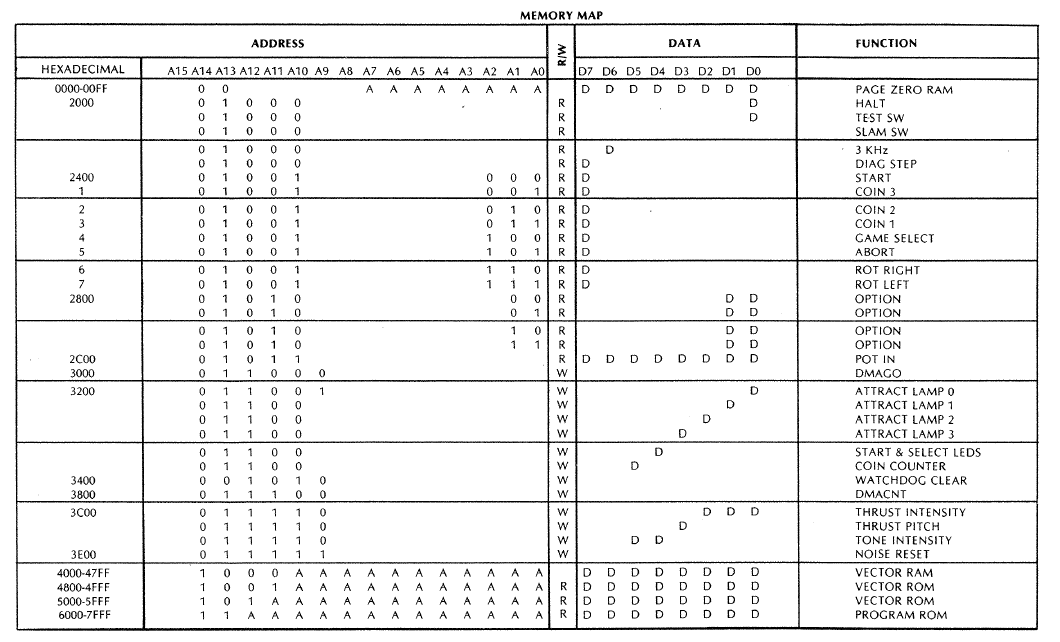
There are five buttons on the controls, Rotate Right, Rotate Left, Abort, Start and Select.
These are all memory mapped into the 6502's address space and set bit 7 in the byte
when they are pressed.
The lamps and sounds are also memory mapper peripherals. Eight output pins are mapped to the
one address. The system caches the last value to avoid read-modify-write problems with this location.
To avoid read-modify-write cycles when updating the lamps or audio devices, the game keeps track
of the last value written in a global variable and uses that as its cache. The functions take two
parameters and act as a SET and RESET value.
; Return 0 if neither or both buttons are pessed, -1 for right, +1 for left
This could also be rewritten into something like C:
volatile uint8_t * const IO_button_right = (void*) 0x2406;
volatine uint8_t * const IO_button_left = (void*) 0x2407;
int IO_read_rotate_buttons(void)
{
  int yaw = 0;
  if (*IO_button_right & 0x80)
    yaw--;
  if (*IO_button_left & 0x80)
    yaw++;
  return yaw;
}
We now know something about the way the game tracks orientation and that it uses a reference frame where positive
rotation is to the left.
Based on the cross references, we can see that this function is called by the ship_command_yaw and ship_command_yaw_easy
functions. Let's look at that first one since it's "easier":
Yaw (Easy)
; Control the ship's yaw by adjusting the angle.
; In the three easy modes the player only controls the rotation angle of the ship
; with the rotate left and rotate right buttons.
; In the easiest mode the ship is limited to mostly upright angles.
;
; Yawing does cost a small amount of fuel and there is a tail call
; to yaw_drain_fuel.
;
Note that the last instruction in the function is a BNE, even though a constant non-zero value has just
been loaded into Y, so it becomes an always-taken relative jump. This is one byte shorter than
the equivilant JMP instruction.
; Shared RTS instruction used by several functions
Another way that programmers saved memory was by reusing instructions across different functions.
The "function" at 63d3 is a single RTS instruction that other nearby functions use
instead of having their own RTS. This complicates the control-flow analysis of tools
like ghidra and sometimes requires manual annotation to decompile.
Yaw (Hard)
; Missions are selected with the "Game Select" button and range from 0 - 3:
;
; 0 "Training" Light gravity Friction Controlled Rotation
; 1 "Cadet" Moderate gravity No Friction Controlled Rotation
; 2 "Prime" Strong gravity No Friction Controlled Rotation
; 3 "Command" Moderate gravity No Friction Rotational Momentum
;
; ship_command_yaw handles the hard yaw mode in difficulty 3 "Command"
; where the player controls the yaw thrusters, rather than the angle.
; this allows the ship to rotate all the way around and they have to stop
; rotation by firing the opposite thruster. it's really hard!
;
; if the game is in a lower difficulty mission, then ship_command_yaw_easy will
; be called instead.
Most of the ship's state is stored in zeropage global variables. These include the
XY acceleration (stored as 17-bit signed magnitude), the velocity and position
(stored as 9-bit signed magnitude?)
The mult16 function is used to compute the ship's X and Y acceleration based on the current thrust,
a thrust-to-force lookup table, and then multiplying by the sine and cosine of the ship's angle to
rotate the force into the screen coordinate frame.
; Update the ship's acceleration in the screen reference frame
; Compute sin and cos of the ship's angle and multiplies the
; current thrust setting to get the X and Y acceleration.
; Also computes the sign bit for these accelerations
Now that we have the math functions for computing signed magnitude addition and transforming
the thrust vectors into the XY screen coordinate frame, we can finally update the ship's position.
; Update ship acceleration, velocity and position in the XY frame once per clock tick
;
; The 16-bit velocity is normally divided by 256, but if the screen is zoomed in
; then it is only divided by 64. Since the NMI runs at 250 HZ, this division
; effectively is the same as multiplying the velocity by dt.
;
; This updates the ship position on each axis
;
; x = x + vx * dt
; vx = vx + thrust_x * dt
; y = y + vy * dt
; vy = vy + (thrust_y - gravity) * dt
;
; add16_signed_mag_arg1 is used for position update since the position sign is always positive
; add16_signed_mag_core is used to accumulate the thrust_y - gravity plus velocity
;
The player has a large lever that controls the thrust from the ship's engine.
More thrust burns more fuel and the game rewards good landings with more fuel.
Fuel
The fuel is stored in BCD format, which means that each byte can represent up 00 - 99, so a
three byte value can represented 000000 to 999999. The 6502 has a special mode in the ALU that
causes addition and subtraction to produce results in this format. Games often used it
for scores since they wanted to display a base-10 value for the player.
; The remaining fuel is stored as a 3-byte BCD amount,
; which gives a maximum of 6 digits in base 10.
; It is stored in reverse order, so fuel_tank[0] is the LSB and fuel_tank[2] is MSB.
Various functions in the code will spend fuel, and they either call fuel_drain_16 to drain a
two-byte amount, or the full fuel_drain that takes a three-byte amount. This is in BCD and
the A:X:Y calling convention is different from some other functions that work on multi-byte arguments.
; Drain a 16-bit BCD X:Y amount of fuel from the ship.
; This tail calls into fuel_drain
This is what makes the Atari arcade games from this era so special -- the vectors instead of pixels!
The actual drawing is done by specialized hardware, which is well documented in
Jed Margolin's "Secret Life of Vector Generators"
and come in two varieties: analog and digital vector generators. Lunar Lander has the DVG,
which is built out of DACs that steer the CRT's electron beam around.
The DVG implements its own little programming language with scaling, subroutines, and brightness control.
The Hitch-Hacker's guide to the Atari DVG by Philip Pemberton
has a good description of how they work, some of which is excerpted here. The main features of the DVG are:
12-bit program counter
4 level stack
Vector timer
12-bit multipliers
4-bit (16 level) brightness control
1024x1024 resolution (10-bit DACs)
Commands are 16-bits long, with the exception of VCTR and LBAS. The first nibble is the opcode so it is easy
to visually tell what is going on.
The main commands that are used in Lunar Lander are:
VCTR (0x0 - 0x9, 32-bit) Draw long vector from the current position to the new XY position
LABS (0xA, 32-bit) Move the beam to the new XY position and set global scale factor
HALT (0xB) Halt the generator and blank the screen
JSRL (0xC) Jump to a subroutine (stack is only 4-levels deep)
RTSL (0xD) Return from subroutine
JMPL (0xE) Jump to an address
SVEC (0xF) Draw a short vector from the current location to a new relative XY position
The vector generator shares memory with the 6502. It has RAM from 0x4000 - 0x47FF and two ROM's
from 0x4800 - 0x4FFF and 0x5000 - 0x5FFF (in the 6502's address space).
Once the 6502 has written a "frame" to the vector generator's RAM, it drives IO_DMAGO which tells
the vector generator to start executing from the RAM until it hits a HLT opcode.
; Draw a single digit
; This will skip leading zeros when outputing numbers.
; A bottom four bits are the BCD digit to draw
; C include leading zeros if clear
The font table is stored in the vector generator's ROM; note that all of their addresses are offset by 0x4000
since it is mapped into the 6502 at 0x4000 but at 0x0000 in the DVG, and that all of the addresses are *words*,
not bytes, so the CADF command is a subroutine call to word 0xADF, DVG address 0x15be, or 6502 address 0x55be
; The characters are stored in the order ' ', 0 - 9, A - Z
Using our emulator for the DVG, we can render out this font table as an SVG:
Each character is it's own DVG subroutine. For example, here is the routine that draws A -- you can see
that it consists of a few short vectors (command F) and then a RTSL (command D) to return:
Text strings are drawn as a sequence of DVG subroutine calls, each character is a DVG JSRL subroutine call
copied from the CharPtrTbl to the vector generator RAM. The strings are stored not in ASCII, but with
the offsets into the font table of the character subroutine call, and the last character in the string
has the high bit set as a terminator.
; Pointer to character in a string being copied to vector ram
; DrawString
; X:Y Pointer to the string to write, terminated with 0x80 on the last character
; Copies the font subroutines to VecRamPtr
; Sets draw_string_ptr to point to the end of the string
The fixed strings are written to the screen by the WriteText function, which also handles localization and
some sort of fixup that I haven't figured out yet:
; Write a localized string to the screen
; A String id
There are 33 strings in the game and they are all indexed by number. For English the table has the pointers,
note that string number 17 is an index into string 16 to reuse the word DESTROYED.
On the 6502 global variables are often stored on the "zero page" since it is possible to reference
the bottom 256 bytes of memory with shorter instruction sequences. It is initialized to zero or
a static value in the RESET code.
This is interesting because it has to deal with potential (physical) attacks on the coin slots,
which apparently was a problem with some other arcade cabinets. The memory mapped coin detectors
are discussed in the button handling section.
; The coin drop switches are only valid if they have been through
; 16 debounce timers, which is 16 * NMI/8, or about 0.5 seconds
; Track how often the coin handling routine is called
; There are three coin buttons with active high coin detectors.
; They are potentially bouncy, so timers are used to try to avoid multiple triggers.
; And the player might be slamming the cabinet to try to trigger the sensor,
; so also check the vibration sensor.
;
; Note that only the two coin slots are used (0 and 2)
;
; Returns a set carry flag if a coin was detected.
;
The mainboard is configured with an external timer that is running at 250 Hz and triggers and
NMI that is used to drive the main timing
loop. When an NMI is received, the 6502 will push some state on the stack, read the pointer
from 0xFFa and jump to that address
; NMI Handler invoked at 250 Hz
; This is the core game tick that invokes all of the ship updates and reads from the player.
; It ensures that the vector drawing system is making progress
; and also pets the watchdog to ensure that the system doesn't reset.